We have used effects in the first hands-on chapter. In this chapter we will tell you how to master them.
In chapter 2 we also listed all the objects available in ROTOR. The following list is a subset that now includes only the effects.
| Family | IN and OUT | Type | # | Subtype |
| Sound Effects |
Multiple audio INs from simultaneous sound generators and/or sound effects Multiple control INs from simultaneous controllers One audio OUT (to an effect or to the final audio sink) |
Filter | 2 | Low-pass filter |
| Band-pass filter | ||||
| High-pass filter | ||||
| Time-based effects | 2 | Delay with feedback | ||
| Beat repeater | ||||
| Reverb | ||||
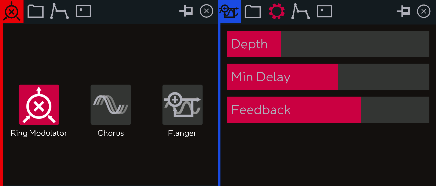
| Modulator | 1 | Ring modulator | ||
| Chorus | ||||
| Flanger | ||||
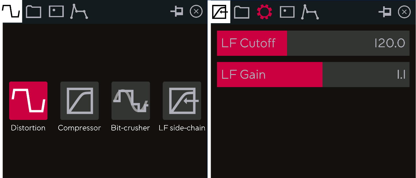
| Waveshaper | 1 | Distortion | ||
| Compressor | ||||
| Bit-crusher | ||||
| Low frequency side-chain compressor |
In this chapter we will start by covering aspects common to all effects, and we will conclude covering each of them in detail.
Effects can receive their input from a generator or from another effect. The previous table also reminds us that effects can have multiple audio inputs as well as multiple control inputs . However, their output can only be sent to one object, which can be another effect or the final audio sink.
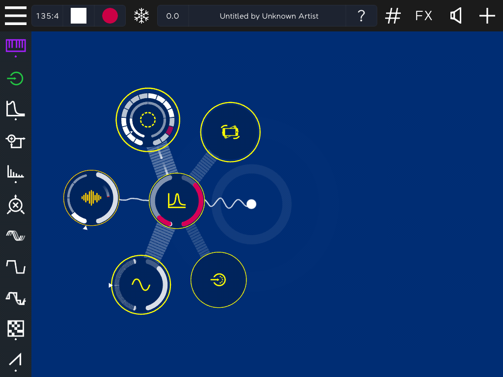
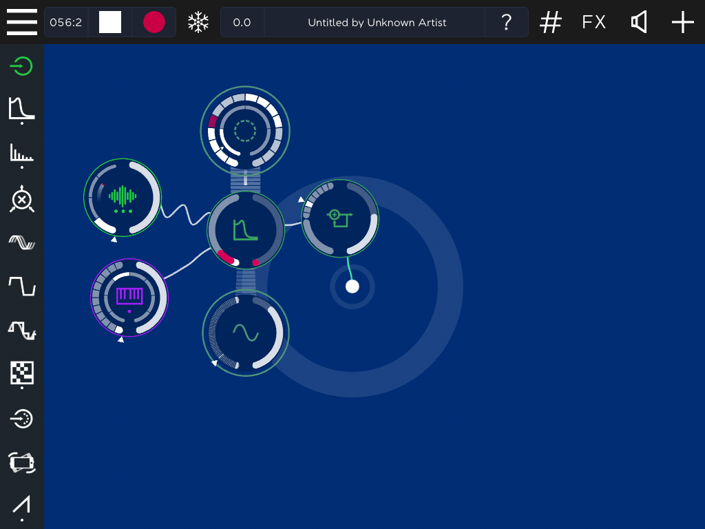
An effect (filter) with 2 audio INs (loop+sampler) and 2 control INs (sequencer+LFO), sending its OUT to another effect (feedback delay).
ROTOR effects can also be used to process audio coming from the microphone, the line in connector or from other apps. This is achieved using the Audio Input object. Although this object does not belong to the Effects family, we introduce it in this chapter, because it becomes more interesting when used in combination with effects.
By default, the Audio IN object will receive its input from the microphone of your iPad. This is handy for making quick and fun voice processing effects, such as in this demo. Bear in mind though that if you use the microphone and the speaker of your iPad at the same time, you will very easily get an annoying feedback. So it better to try these effects using headphones.
Before discussing effects separately, in this section we will cover the different ways provided by ROTOR for controlling these effects.
Independently of their type, all ROTOR’s effects share many commonalities, specially when we consider control. They all have a:
Additionally, they all admit additional real-time control coming from:
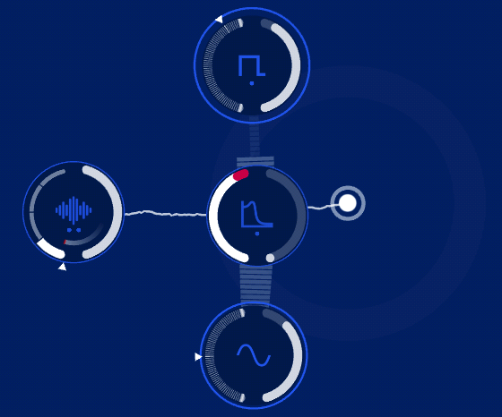
An effect (filter) receiving all possible simoultaenous controls (sequencer, accelerometer, MIDI IN and LFO)
Points 1, 2, 3 and 4 do probably not need further explanation. We will now address the remaining ones.
All effects configuration panels include a tab for 1-finger 2D control. Moving our finger on one of these panels, we can listen but also watch the effect provoked on its associated object. We will be able to observe how the values of the object’s left and right circular slider vary, following our finger.
TIP : In 1-finger 2D control panels, the x coordinate tends to control the associated effect left slider value and the y controls the right slider one.
When using rotor controllers on these panels, 2D becomes indeed 3D control, because the rotation angle of the rotor is added to the x-y position! The parameter associated with this 3 rd degree of freedom (DOF) varies with each effect. When retiring the rotor from the panel, the value of this 3 rd parameter will stay constant until we touch again the panel with the finger, in which case, this 3rd parameter will return to a predefined default value.
1-finger 2D control can be a very expressive tool; rotor 3D control can even be more expressive!
You can load this demo, open the panels for the delay and distortion objects and experiment with (3DOF) and without (2DOF) rotor controllers.
Many popular effects in electronic music use some type of modulation for producing sounds that periodically change in time, and the most common way to obtain this is to apply Low Frequency Oscillators (LFOs) to some parameter. Low-frequency oscillation is an electronic signal which is usually below 20 Hz and creates a rhythmic pulse or sweep. This pulse or sweep is often used to modulate synthesizers, delay lines and other audio equipment in order to create effects used in the production of electronic music. Audio effects such as vibrato, tremolo and phasing are examples.
Low-frequency oscillation as a concept was first introduced in the modular synths of the 1960s and 70s, and are present in some form on almost every synthesizer of today, including of course, ROTOR. This is in fact not the first time we mention ROTOR’s LFOs. We have cited and used them in every single chapter until now! We first introduced them in section 1.5 where we modulated a low-pass filter with a low frequency sine wave. We mentioned them in section 2.4.3 when we listed all controllers available in ROTOR, and we finally applied them to different types of looper players in section 3.8.3. That said, because since the early days of electronic music, LFOs have been widely associated with filter control, time has finally arrived for describing them in detail.
Like all periodic signals, LFOs are described by three parameters, their waveform, their frequency and their amplitude.
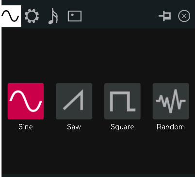
In ROTOR, like in most synthesizers, the available waveforms include:
All these are available from the LFO main panel:
The 4 available waveform subtypes
Note that there is no special icon for the triangle waveform. This is because in ROTOR, this waveform (and other variations) can be created from the sawtooth waveform, as we will see soon.
In ROTOR, the LFO frequency is controlled from the object’s left slider, which means that rotation changes the frequency, and the amplitude on the right slider.
While on most synthesizers, the LFO frequency tends to range from ~1/10 Hz or less, to around 20 Hz, in ROTOR this control is BPM-dependent, meaning that if desired, ROTOR LFOs can easily play synchronized to the beat.
The scale displayed when moving the right slider or rotating the object ranges from 64, the slowest value which corresponds to a period of 2 bars, to 1, the fastest value corresponding to a period of a 1/32 nd note. The next table indicates some of the note values corresponding to the numbers shown on the LFO left slider, and their resulting frequency values at a tempo of 120 BPM.
|
Scale |
Note value |
Frequency in Hz at 120 BPM |
|
1 |
1/32nd note |
16 Hz |
|
2 |
1/16th note |
8 Hz |
|
4 |
1/8th note |
4 Hz |
|
8 |
1/4th note |
2 Hz |
|
16 |
1/2th note |
1 Hz |
|
32 |
Whole note (1 bar) |
0.5 Hz |
|
64 |
Double note (2 bars) |
0.25 Hz |
Controlled from the object right slider, the amplitude ranges from 0 to 1. When the amplitude is set to zero there will be no modulation effect (i.e. like having no LFO). When set to 1, the modulation effect will be maximum. The modulation effect controls the amount of variation applied to the parameter to which the LFO has been connected.
You can load T41 FilterLFO which has a loop player going through a resonant filter which is being modulated by a sine LFO.
If you pay attention to the animations displayed on the LFO object, you will also observe that:
If you are not sure about what we are saying, switch to a square waveform to observe how these two animations change now abruptly (unlike the sine wave, which grows and shrinks continuously, the square wave has only 2 possible values).
Compare the square (top) vs the sine control wave (below)
TIP : ROTOR’s animations are not merely decorative. They are meant to be informational, by displaying all the activity passing through the objects as accurately as possible. This is both true for the waveforms, for the control data information and the animations on the objects themselves.
Like effects, the LFO panel has also a 2D tab, and as with effects, the x value is mapped to the left slider (now the LFO frequency) and the y value to the right one (the LFO amplitude). So if you enjoyed fiddling with the 2 controls in the previous example, you can now do the same with just 1 finger!
Using the last example, you can now open the two 2D pads (the filter’s and the LFO’s) and modify the 4 parameters at once using only two fingers.
When using a rotor, the 3 rd degree of freedom that will be controlled by rotation is the sample & hold duration, which we document next.
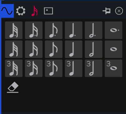
Like sequencers and other controllers, LFOs also have a duration panel, which in this case allows to control the sample and hold factor . Sample and hold is a mechanism which was already implemented in many of the 1960s analog synthesizers, and which is used for discretizing continuous signals, thus converting a continuous modulation into a stepped one.
LFO durations panel
In the previous examples we have used the LFOs in their default, continuous behavior. This continuous mode is set in the panel by touching the eraser icon. Otherwise, all other note values determine the step duration, always relative to the current BPM, at which the LFO values will be sampled.
TIP : By controlling the sample and hold duration of the LFOs, effects will change at step rates which will always be synchronized to the beat.
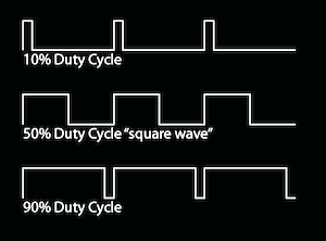
This panel brings three parameters that modify the waveform.
Varying the duty cycle in a square wave
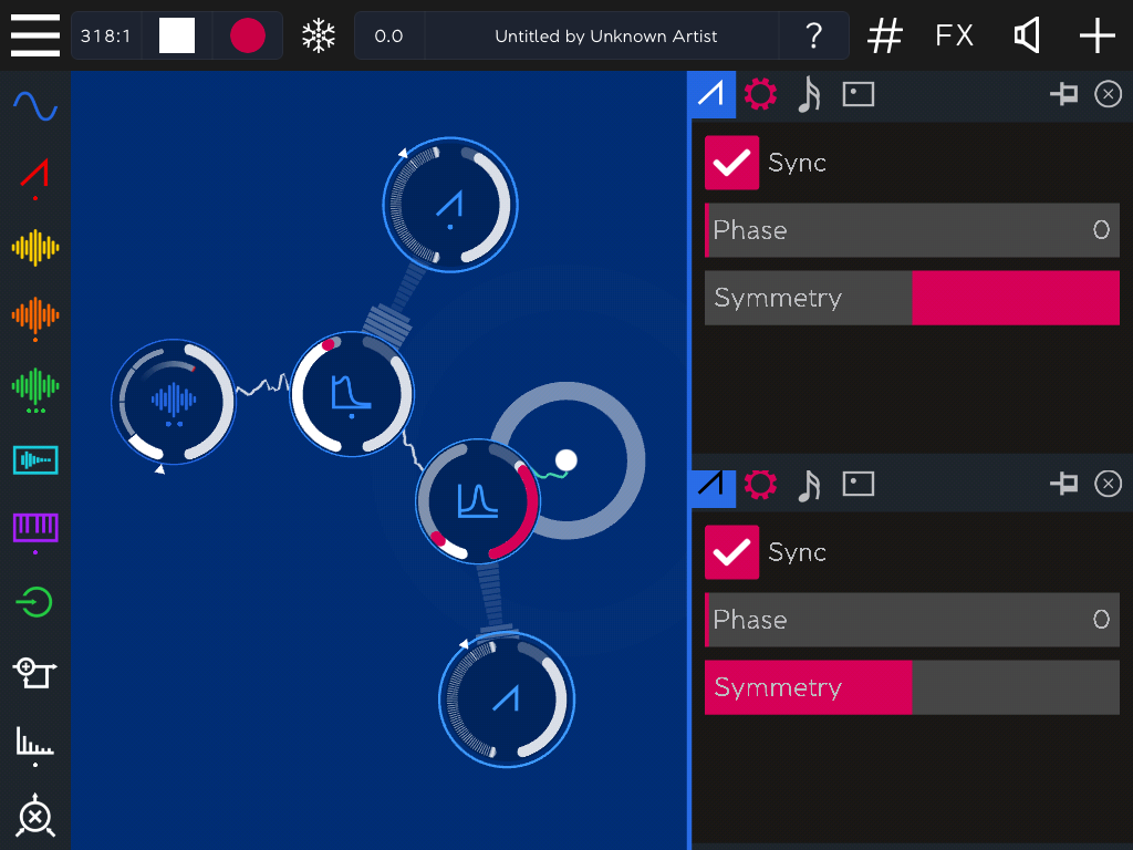
TIP : Playing with the symmetry parameter on an LFO sawtooth waveform will allow us to navigate from an increasing sawtooth (symmetry left) to a decreasing one (symmetry right), passing through a triangle waveform (symmetry center). This is reflected in the following figures, in which we can appreciate how the shape of the 3 control connections varies depending on the symmetry value.
Compare the shape of the two sawtooth LFOs, considering their Symmetry. In the top one control values increase (from 0 to max), while in the bottom one they decrease (from max to 0).
As we have already mentioned in 4.2.1, all effects include an additional Envelope tab. We have not used this tab until now, because envelopes only enter the game when the associated effect is triggered by a sequencer. For a detailed documentation of both sequencers and envelopes we recommend to read next chapter’s sections 5.5 and 5.7.4, where the two concepts are discussed in full detail. For now, we will just tell you how they apply effects.
Applying envelopes to effects, specially to filters, is a common technique widely used in electronic music. It is for example the main responsible of the fast evolving “acid” sound of the Roland TB-303 bass synthesizer, so much used in styles such as Acid House and Techno.
Load this acid style Demo.
Now that we have covered all the aspects common to all types of effects available in ROTOR, we will conclude this chapter by studying each type of effect in particular. We will start with filters.
ROTOR includes 2 objects of the filter type, which can be configured according to 3 subtypes :
|
Type |
Objects |
Subtype |
Left parameter |
Right parameter |
Additional parameters |
|
Filter |
2 |
Low-pass filter |
Cutoff frequency |
Resonance |
0 |
|
Band-pass filter |
Resonant frequency |
Resonance |
0 |
||
|
High-pass filter |
Cutoff frequency |
Resonance |
0 |
None of them has any additional settings.
ROTOR includes 2 time-based effects objects, which can be configured according to 3 subtypes:
|
Type |
Objects |
Subtype |
Left parameter |
Right parameter |
Additional parameters |
|
Time-based effects |
2 objects |
Delay with feedback |
Delay time |
Dry/wet |
5 |
|
Beat repeater |
Repeat time |
Dry/wet |
3 |
||
|
Reverb |
Reverb time |
Dry/wet |
2 |
Following we describe the specificities of each of them.
The delay time on the left slider, is divided into two sections:
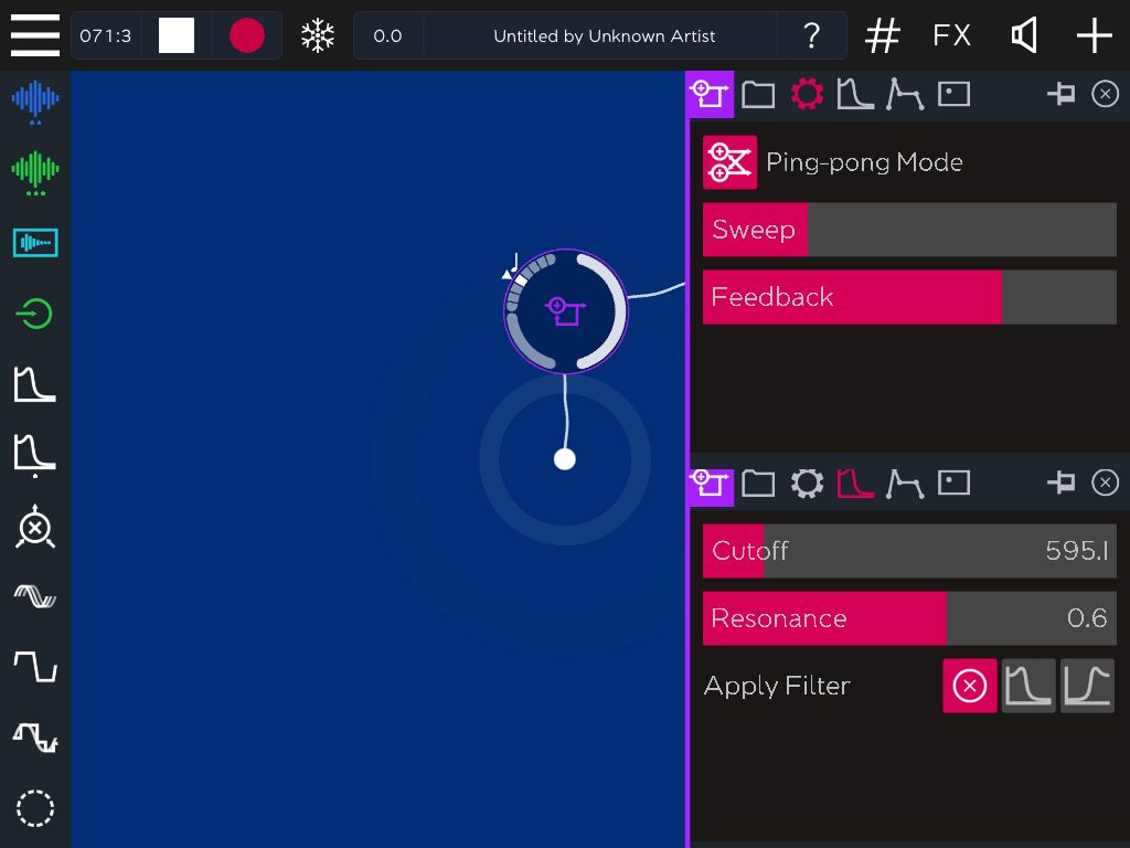
Figure showing the 2 ranges of the delay left slider (left), the main settings panel (top) and the filter settings panel (bottom).
This effect has 6 additional settings, accessible from 2 tabs:
TIP : When applying a sequencer to the feedback delay, the pitch of each note in the sequence will affect the delay time and the amplitude of each note will affect the feedback. Experiment applying LFOs and/or sequencers for unexpected and surprising effects!
The filter tab allows to configure optional filtering to the feedback signal:
TIP : ROTOR’s beat repeat, combined with the modular control possibilities offered by LFOs and sequencers, is a truly amazing effect that overshadows many related VST plug-ins that cost 10 times more than the whole ROTOR app!
Unlike delays, that keep continuously delaying their input signal, what the basic beat repeat does is sampling a fragment of its input and keep repeating it several times, at a rate equal or smaller than the duration of the sampled fragment. So you basically need to control: (1) when to sample, (2) for how long, (3) how many times to repeat the sampled fragment and (4) at which rate. A typical effect is obtained by progressively shortening the fragment being repeated (i.e. 4 th parameter).
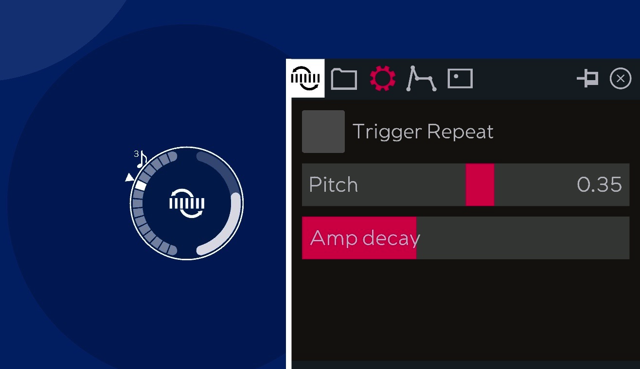
In ROTOR’s Beat-repeat object:
the sampling duration (or repeat time) is controlled by the left slider. These durations are BPM dependent and quantized according to note values, ranging from the longest quarter note (¼ or♩ ) at the top of the scale, to the shortest 1/48 of a quarter note (or 1/48 of a beat) at the bottom of the scale.
The Beat-repeat object and its settings panel